Pitch Damping, Mooring Reposition — Same Kind of Control?

Pitch Damping, Mooring Reposition — Same Kind of Control?

| collective blade pitch animation | mooring reposition animation | | — | — |

The FOWT digital twin from my previous post could only watch the platform — it ran a co-simulation, plotted the result, and told you whether the mooring held, but it never changed how the platform actually behaved. This post adds two things that do, and it’s worth being precise about that claim before looking at either: “adds control” doesn’t mean the same thing for both of them.


Two Kinds of Control

Pitch damping and mooring reposition sound like the same kind of upgrade — both take a parameter and change how the platform responds — but they act on the simulation in two structurally different ways.

The pitch controller is genuinely closed-loop. Once switched on, it runs inside run_cosim, every timestep: it reads the platform’s current pitch angle and reacts in real time, for the rest of that run. The off mode it replaces never looked at platform motion at all — it only ever looked at wind speed. This one also has a real-world anchor: gain-scheduled pitch PI with a rate-feedback (“floating feedback”) term is the documented design pattern behind NREL’s ROSCO reference controller (Abbas et al., 2022, 10.5194/wes-7-53-2022) — the mechanism below mirrors deployed practice, not a hypothetical.

The mooring solver is not closed-loop. reposition_mooring never touches a running simulation. It reads a finished run’s steady-state offset, solves for new line lengths, and stores them in the session’s configuration. The platform doesn’t move — the configuration for the next run_simulation call does. Mechanically that’s the same shape as picking any other simulation parameter — Hs, Tp, U_hub — and running again. What’s new is that the number it picks now comes from solving an optimization over a real prior result, rather than being chosen up front. Unlike pitch damping, this one has no comparable anchor in deployed hardware: no operating floating turbine actively retensions its lines to counter thrust — see the caveat later in this post. Treat that part of this post as a “what if” exploration of an idea that shows up in research, not a description of existing practice.

Neither one commands anything outside the simulation. Pitch damping changes behavior only inside a running FMU; mooring reposition changes a stored configuration for the next run. An engineer still decides whether to actually retune a real controller or move a real mooring line — what’s simulated here is what happens if you do.


Where the Controller Lives

Neither off nor pi runs inside the FMU. The FMU — FOWT.fmu (or FOWT_linux.fmu on Linux; same model, a different OMC build, since the two platforms’ FMI binaries aren’t interchangeable) — is a compiled FMI2 co-simulation slave built from FOWT.mo: platform rigid-body dynamics and Blades.mo’s thrust/pitch actuation, nothing about a controller in it. The controller is plain Python: control/pitch_pi.py’s GainScheduledPitchPI class for pi, a one-line closed-form formula inline in simulation/cosim_runner.py for off. Both are stepped from outside the FMU, once per timestep, by the co-simulation driver, run_cosim().

Here’s how everything talks to everything else — the controller, the FMU, and the 3 mooring lines that close the loop back into it:

flowchart LR
    subgraph LOOP["Python: simulation/cosim_runner.py -- run_cosim()"]
        WIND["WindModel\nenvironment/wind_model.py"]
        WAVE["WaveModel\nenvironment/wave_model.py\n+ loads.py"]
        CTRL["PitchController\ncontrol/pitch_pi.py\n(Python, not Modelica)"]
        GEOM["line_geometry.py\nforce resolution"]
        MOOR["MooringLine i (x3)\ncatenary or onnx"]
    end
    FMU[["FOWT.fmu\nFMI2 slave (FMPy), from FOWT.mo"]]

    WIND -- "windSpeed(t)" --> FMU
    WIND -- "V(t), same signal" --> CTRL
    WAVE -- "waveForces[1]" --> FMU
    CTRL -- "pitchCollective = phi_ref" --> FMU
    FMU -- "pitch (step i-1)" --> CTRL
    FMU -- "surge,sway,heave,\nroll,pitch,yaw (step i-1)" --> GEOM
    GEOM -- "horizontal_offset" --> MOOR
    MOOR -- "fairlead_tension_N,\nhorizontal/vertical_force_N" --> GEOM
    GEOM -- "forceML1/2/3[1..3]" --> FMU

Rectangles are plain Python objects; the double-bordered block is the compiled FMU — the only non-Python piece in this loop. pitchCollective, windSpeed, waveForces[1..3], forceML{1,2,3}[1..3], and the 6 surge...yaw outputs are the FMU’s actual FMI variable names, set and read through FMPy each doStep() call.

Two things about this loop aren’t obvious from the picture. First, windSpeed reaches the FMU and the controller as the literal same instantaneous, turbulent signal — nothing here simulates an anemometer or a LIDAR; pi’s own low-pass filter (next section) is what stands in for a real sensor’s bandwidth limit, not a separate measurement model. Second, the loop is one step behind on purpose: the controller and the mooring calculation both read the FMU’s motion outputs from step i-1, never the step about to be computed. That’s a standard explicit (Jacobi-type) co-simulation coupling — each macro step gets evaluated once, not iterated to a fixed point — and it’s also why mooring needs line_geometry.py in the middle at all: each MooringLine instance only knows a scalar horizontal offset, so something has to turn 6 platform DOFs plus fixed anchor/fairlead geometry into that scalar, then turn the returned tension back into 3 force components per line before forceML{1,2,3}[1..3] can go back into the FMU. Swapping CatenaryMooring for OnnxMooring — Part 1’s neural-network surrogate for the same catenary solve — changes nothing else in this diagram; line_geometry.py calls .compute(horizontal_offset) on whichever one it’s given.


Regulating Pitch

The diagram above shows how the controller connects; this one shows what’s actually inside it, as a standard control-block diagram — generic blocks, not a schematic of any real code file.

flowchart LR
    V["wind_speed V(t)"] --> OFFFN["Function<br/>off: static feedforward"]
    OFFFN --> OFFCMD(["off: phi_ref"])

    V --> LP1["Low-Pass Filter<br/>T = 2.0 s"]
    LP1 --> VF(["V_filtered"])

    VF --> FF["Function<br/>same Region-3 law as off"]
    VF --> SCHED["Gain Schedule<br/>DEFAULT_SCHEDULE<br/>-&gt; Kp, Ki"]
    VF --> FLSCHED["Gain Schedule<br/>DEFAULT_FL_KP_SCHEDULE<br/>-&gt; fl_kp"]

    PITCH["platform_pitch<br/>(measured, setpoint = 0)"] --> KPGAIN["Gain: Kp"]
    PITCH --> INTEG["Integrator<br/>(conditional anti-windup)"]
    INTEG --> KIGAIN["Gain: Ki"]
    PITCH --> DERIV["Derivative<br/>T = 0.1 s (band-limited)"]
    DERIV --> FLGAIN["Gain: fl_kp"]

    SCHED -.-> KPGAIN
    SCHED -.-> KIGAIN
    FLSCHED -.-> FLGAIN

    FF --> SUM["Summing Junction<br/>(4 inputs)"]
    KPGAIN --> SUM
    KIGAIN --> SUM
    FLGAIN --> SUM

    SUM --> LIM["Saturation<br/>[0, pi/2]"]
    LIM --> SLEW["Rate Limiter<br/>8 deg/s"]
    SLEW --> PICMD(["pi: phi_ref"])

Generic control-block vocabulary, not a schematic of the source. The whole thing is GainScheduledPitchPI.step(), ~60 lines of Python, called once per timestep from outside the FMU — nothing here runs as a block diagram, this is just a clearer way to describe what the code does than prose alone. One block is worth flagging: Integrator’s anti-windup is a simple conditional freeze (stop accumulating whenever Saturation or Rate Limiter is actively clamping), not a textbook back-calculation scheme.

off isn’t a zero-pitch stub — it’s the exact closed-form Region-3 law Part 3 shipped with: above rated wind speed it feathers the blades by a fixed formula of wind speed alone, φ = (π/2)·(1 − (V_rated/V)²), holding thrust near its rated value. It has no idea the platform is floating — it would compute the exact same pitch angle on a fixed-bottom foundation.

My first version of GainScheduledPitchPI replaced that formula outright: a plain PI loop on platform pitch, command = Kp·error + Ki·∫error dt, nothing else. It didn’t work. Above rated wind, dropping the feedforward meant the turbine ran at close to full thrust until the platform had already tilted enough to trigger a correction — always a step behind the disturbance instead of ahead of it. Pitch RMS came out worse than off, not better.

The fix wasn’t a smarter feedback law, it was not throwing away the feedforward. Real above-rated pitch controllers never do — a scheduled baseline holds the mean operating point, and feedback only trims the residual around it. So pi mode adds three terms together:

  • Feedforward — the same Region-3 curve described above, so the mean operating point is right from the first timestep.
  • PI trim — gains interpolated from a wind-speed schedule (DEFAULT_SCHEDULE), correcting the residual error the feedforward alone leaves.
  • Rate feedback — a low-pass-filtered term on platform pitch velocity, the same mechanism NREL’s ROSCO reference controller calls “floating feedback.” Position feedback alone doesn’t add damping to a resonant mode; it was slightly amplifying the wave-frequency oscillation instead of settling it. A term on the rate of tilting is what actually opposes the motion. Its gain is itself wind-speed-scheduled rather than a single constant — more on that below.

The whole command is also actuator-realistic: rate-limited to 8°/s, a real utility-scale pitch actuator’s slew spec. Feeding it raw, instantaneous wind speed would demand pitch changes faster than that actuator can track, so the feedforward, PI gains, and rate-feedback gain all read a low-pass-filtered wind speed (time constant 2.0 s) instead — the same filtered-or-estimated signal real turbine controllers use.

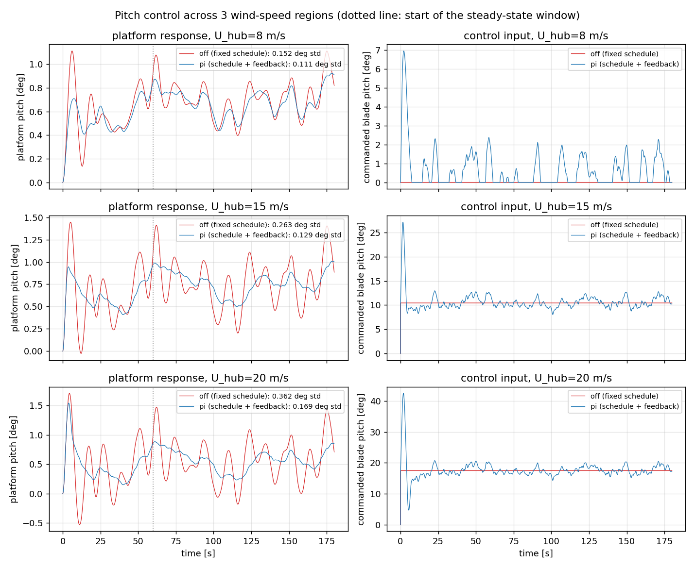
Pitch control, off vs pi: platform response and control input, across three wind-speed regions

120 s runs at Hs=3 m, Tp=9 s, TI=0.10, for three hub-height wind speeds spanning below-rated, near-rated, and above-rated conditions. Left column is platform pitch (the response); right column is the commanded blade pitch (the control input) that produced it. Red is off, blue is pi.

The three regions tell three different stories:

  • U_hub=8 m/s (below rated): pi helps on both axes — pitch RMS drops from 0.880° to 0.799° (about 9%), surge RMS from 4.821 m to 4.656 m (about 3%).
  • U_hub=15 m/s (near rated): pi still helps pitch — 1.525° down to 1.467°, about 4% — though surge RMS actually ticks up slightly, 9.062 m to 9.291 m. The pitch improvement isn’t entirely free.
  • U_hub=20 m/s (above rated): the wind-speed filter did not resolve the disruption. pi is worse than off on both metrics: pitch RMS rises from 1.525° to 1.955° (about 28% worse), and surge RMS rises from 9.062 m to 10.599 m (about 17% worse).

Worth noting: off’s pitch RMS is almost identical at 15 and 20 m/s (1.525° both, to three decimals) — above rated wind, the Region-3 law holds thrust near the same value regardless of exactly how far above rated the wind is, so the platform’s undamped response barely changes with wind speed. pi doesn’t have that property; its behavior diverges sharply between the two regions instead of staying flat. Filtering the wind-speed signal was the right instinct and it is what real turbine controllers do, but a 2.0 s time constant and the existing gain schedules don’t fully tame the coupling between pitch actuation and platform surge once you’re solidly above rated. That’s an open problem, not a solved one — the honest read of this run is “use pi near rated, don’t default to it above rated without more tuning.”


Collective Blade Pitch (CBC)

Every blade-pitch command in this post, off or pi, is collective: one number, pitchCollective, sent to all three blades at the same instant. That’s what the FMU exposes — Blades.mo takes a single phi_ref input, not one per blade — and it’s what the PI trim and rate-feedback terms above were tuned against. Individual pitch control (IPC), where each blade gets its own azimuth-scheduled offset to reject asymmetric rotor loads (1P/2P), is a different, established technique in real turbine controllers — but it needs a per-blade actuation channel and a rotor-azimuth measurement this model doesn’t expose. Nothing in this post does that; every command and every animation moves all three blades together.

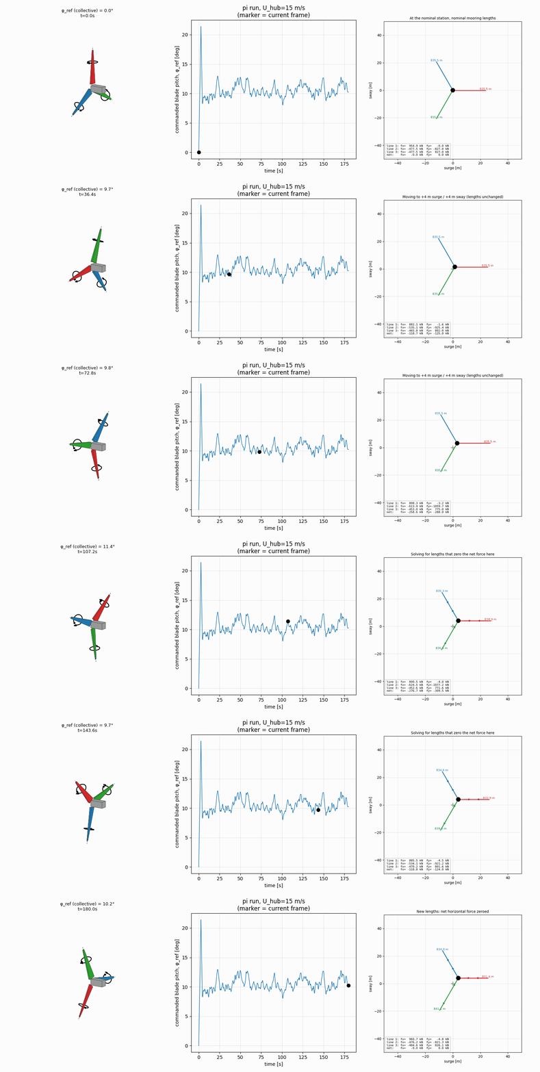
Three blades pitching collectively, driven by the real pi-controller command trace

Schematic 3D nacelle and hub. Each blade is a small tapered box, not a flat quad, so its twist around its own longitudinal axis is visible as rotation, not just a foreshortening quad — the dashed line through each blade is that axis, and the black ring is the twist itself, sweeping by the exact same angle (φ_ref, in the title) on all three blades at every instant, driven by the real pitch_command trace from the pi run at U_hub=15 m/s (the “collective” in the name). Rotor spin is illustrative only and slowed down for visibility; the FMU has no rotor-azimuth output to animate the real rotation from — only pitchCollective in and the platform’s 6 rigid-body DOFs out.

Both gain schedules mentioned above, in full:

Wind speed [m/s]KpKifl_kp
11.40.400.05040
15.00.300.04040
20.00.200.03010
25.00.150.0205

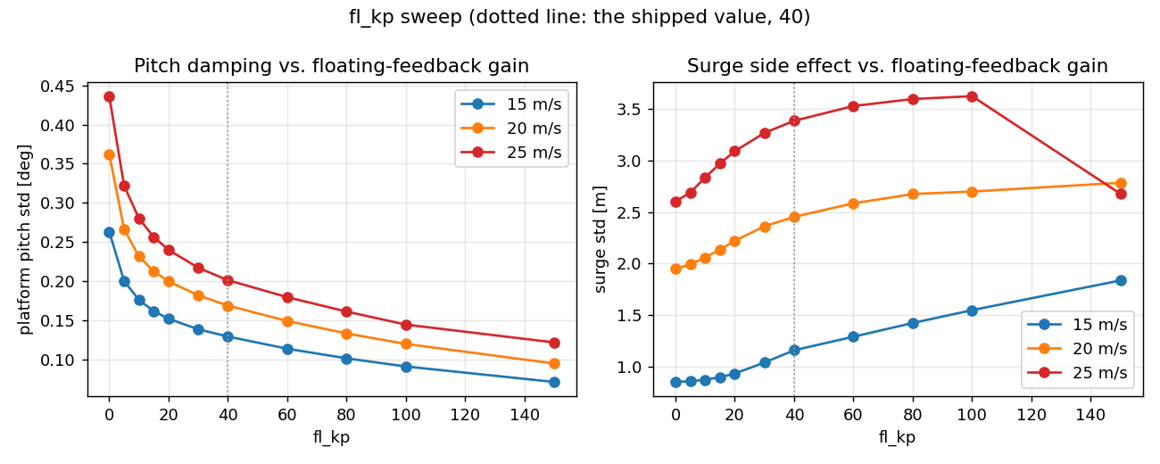
Kp/Ki come from DEFAULT_SCHEDULE, trimming the platform-pitch error term. fl_kp comes from the separate DEFAULT_FL_KP_SCHEDULE — the rate-feedback (“floating feedback”) gain from above, tapered down hard past 15 m/s after it was found to destabilize surge at U_hub=20 (see the region breakdown above). Both were set by a coarse manual sweep against a handful of scenarios, not a rigorously optimized design — linearly interpolated between breakpoints and clamped outside the table’s range.


Repositioning

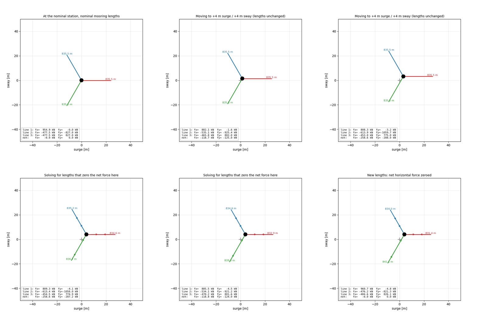
Before any solver or baseline run, the core mechanics check out by hand: pick a target station, and ask what net horizontal fairlead force the current mooring produces there. At the nominal 835.5 m per line, sitting at +4 m surge / +4 m sway already produces unbalanced forces — fx of 774.7 kN / −659.5 kN / −447.0 kN and fy of −3.9 kN / −1137.5 kN / 762.0 kN across the three lines, net (−331.8 kN, −379.4 kN), not zero. So that’s not a station the nominal lines can hold on their own — something external has to supply that force. On a real turbine, that something is rotor thrust: the aerodynamic load pushing the turbine (and platform) downwind, which the mooring’s tension has to counterbalance for the platform to sit still anywhere off its natural rest position.

Solving for lengths that zero the net force there, while changing each line as little as possible from nominal, gives 831.4 m / 841.1 m / 834.0 m — deltas of −4.1 m, +5.6 m, −1.5 m — and the net force verifies to zero (fx and fy both ~1e-9 N, to numerical precision), with tension coming out naturally even, around 1.15 MN per line, no slack needed. That’s a static check only — nothing here has run through the simulator yet, so whether it actually holds station under real wind is still untested. Keep that in mind for what follows.

Moving to +4/+4 m under nominal lengths, then adjusting lengths to zero the force

Nothing physical happens here, it’s the solve, not a simulated transient. The platform moves from the origin to +4 m surge / +4 m sway under unchanged nominal 835.5 m lines — the per-line and net fx/fy readout in the corner shows the same unbalanced net (−331.8 kN, −379.4 kN) computed above. Lines then adjust to 831.4 m / 841.1 m / 834.0 m, and the net column drops to ~0 kN. Arrows show each line’s direction of change during that adjustment; length changes are exaggerated on screen (real deltas are a few meters against an 835.5 m line) — labels show the real lengths.


Counterbalancing Thrust with the Mooring Lines

The static check above raises an obvious question: if a mooring line’s length determines how much horizontal force it can hold against, and rotor thrust is a roughly known, slowly-varying load, what if you deliberately paid out or hauled in line to offset it — trading a length change against a thrust load instead of just accepting the offset? That’s a “what if,” not a description of how any real floating turbine is operated today; the hardware to move a line exists, but using it this way, in real time, against thrust, doesn’t (caveat below). What follows is a demo of the idea against the digital twin, not a claim that it’s how the industry does this.

flowchart LR
    run1["Baseline run<br/>(nominal lengths)"] --> offset["Steady-state<br/>offset"]
    offset --> solve["Solve for new line lengths<br/>(SciPy SLSQP)"]
    solve --> lengths[New line lengths]
    lengths --> run2["Next run<br/>(new line lengths)"]
    run2 --> platform[Platform recentered]

No feedback loop here — this is a one-shot pipeline. A finished run’s offset goes in, new line lengths come out, and nothing runs again until you start the next simulation with them.

reposition_mooring solves a smaller, more classical problem: given a sustained environmental force, what three line lengths let the platform sit in equilibrium back at its nominal station? It reuses mooring.catenary_mooring.CatenaryMooring as the per-line forward-force model — one instance per line, each with its own trial length — rather than reimplementing catenary physics, and minimizes the variance of fairlead tension across the three lines subject to a force-balance equality constraint, via SciPy’s SLSQP.

This demo run has pi pitch control explicitly turned on via configure_pitch_controller before either simulation, the same mechanism the pitch-region comparison above uses — not a separate built-in controller. It runs at the same near-rated 15 m/s the previous section already validated as pi’s good region (pitch RMS down, surge RMS only a slight tick up), so this demo isolates the mooring solver’s own contribution rather than compounding it with the pitch-side regression above rated. At U_hub=15 m/s, a baseline run with nominal 835.5 m lines settles into a steady 10.056 m surge offset — the platform living notably off-station under sustained wind. Feeding that run’s run_id to reposition_mooring proposes new lengths (835.5 m / 826.3 m / 826.3 m against that same 835.5 m nominal — line 1 barely moves, lines 2 and 3 each shorten by about 9 m), predicted to hold at 1.15 MN, 1.88 MN, and 1.88 MN of fairlead tension. Running the same environment again with those lengths adopted brings the offset to −1.769 m — overshooting slightly past the nominal station to the other side, but about 82% smaller in magnitude than the 10.056 m baseline.

Surge offset before and after mooring reposition

Same sustained wind, two mooring configurations, both with pi pitch control running. Nominal lengths (red) settle around 10.1 m off station. Repositioned lengths (blue) settle just past zero on the other side — the overshoot is far smaller than the original offset.

Platform drifting, the solver's proposed length adjustment, then recentered

A schematic top-down view of the same two runs: the platform drifting under the nominal lengths, the solver’s proposed lengths ticking in (position held fixed — nothing physical happens at this instant, it’s the solve, not a simulated transient), then the platform recentered — and slightly past center — once those lengths are adopted for the next run. Anchors sit ~840 m out, far past what would fit on this scale — the three lines are drawn schematically toward each anchor’s true bearing, not to true length. Arrows on each line show its direction of change: converging toward the middle for a line getting shorter, diverging toward the ends for one getting longer — in this run, line 1 barely moves (about 0.05 m longer) while lines 2 and 3 each shorten by about 9.2 m to redistribute tension.

If the solve is infeasible — an environmental force too large for any three lengths to balance — it says so rather than returning a wrong answer: {"error": "no feasible equilibrium", "best_residual_n": ...}. That’s exactly what happens if you hand it something like a 50 MN force by hand; SLSQP can’t converge and the tool reports the failure instead of silently proposing lengths that wouldn’t actually hold.

Caveat: this maps onto real hardware only partway. Chain jacks and mooring winches that change fairlead or anchor-side line length are standard offshore kit — used routinely on FPSOs and floating platforms to pretension lines during installation and to null out tension imbalances before final lock-off. What’s not standard commercial practice is using that same hardware in real time to counterbalance rotor thrust the way this demo just did — trading line length against a known thrust load to hold station. Deployed floating wind turbines are moored passively, sized for worst-case loads, and left alone once installed. Active mooring-tension adjustment as a running control strategy shows up in the “smart mooring” research literature (fatigue-load reduction, station-keeping optimization), not in operating turbines today.


Wrap

Two different additions to the same digital twin, and two different reasons they’re not the same kind of “control”: one closes a loop inside a simulation, the other proposes a configuration between two of them. The concrete finding this session is narrower than “filtering fixed it” — feeding a filtered, rather than raw, wind speed into the pitch setpoint is the correct instinct, the same one real turbine controllers use, and it does help below and near rated wind. It does not, on the regenerated data, resolve the above-rated coupling between pitch actuation and platform surge. That’s still exactly the kind of thing a simulation is supposed to let you catch before it’s real: not a demo where everything works, but a simulated consequence disagreeing with the plan.


Code: vedat-s/Automation · part4_active_control/

This post is licensed under CC BY 4.0 by the author.