
The slip reading improves. The web stays off centre. Has more nip force solved the problem?
In this simulated film-winding line, increasing nip load cuts accumulated slip by 66%, while final lateral offset changes by less than 1%.
We use Roll2RollDynamics, an internal Modelica library developed by us, to couple roller motion and elastic web spans with lateral tracking and frictional contact. Its yaw steering and closed-loop tension tracking are checked against published measurements [1–3]; nip contact under crossed or tilted axes, and the runout disturbance demonstrated here, rest on consistency checks only. With tension controls active, we examine nip loading, alignment and friction, then trace a runout disturbance into neighbouring spans. These experiments demonstrate modeling capability using assumed parameters without production line calibration. Numerical results apply to these settings.

Figure 1. OpenModelica diagram view of the UnparallelIdler assembly
connecting unwind, spans, misaligned idler, nip and rewind.
Increasing Nip Load at Fixed Misalignment
Can more nip load restore tracking? A dragging idler bearing needs traction as tension falls. The nip presses the web onto that idler, whose axis is yawed by 20 mrad, about 1.15 degrees. The nip housing remains machine-aligned.
The 600 mm wide, 125 micrometre thick PET web ramps to 2 m/s in 5 s, with 400 N nominal tension. The dancer, tension controller and unwinder feed trim remain active throughout.
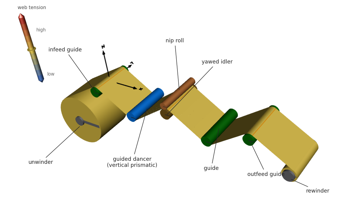
Figure 2. Yawed startup, with the web coloured by tension.
An undriven nip with 50 mm radius and 660 mm face width sits above the
idler on a rigid housing. Full-width stiffness k = 1 MN/m gives
N = kδ = 1000 N at parallel compression δ = 1 mm. Parameter
maxNipLoad = 1000 N denotes maximum actuator force, a limit this
imposed-compression housing does not enforce. Bearing coefficient
b = 0.35 N·m·s/rad, speed v = 2 m/s and idler radius R = 0.075 m
give demand F = bv/R² = 124.4 N. The wrapped web can supply about 177 N
at nominal tension under the assumed friction law, so the contact holds
with 53 N to spare. The post-ramp tension dip reduces that margin.
We hold bearing drag and idler angle fixed, with zero tram and runout. Nip housing compression changes from clear to 0.25, 0.50, 0.75 and 1.00 mm.
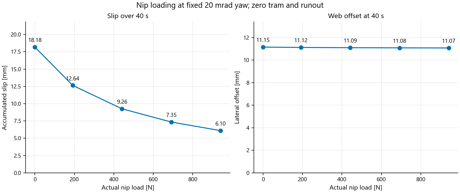
Figure 3. At fixed misalignment, accumulated slip decreases by 66.4%; final lateral offset decreases by only 0.7%. Both vertical axes start at zero.
Over 40 s, increasing contact load from zero to 942 N cuts accumulated slip from 18.18 to 6.10 mm. Offset stays about 11.1 mm, changing by less than 0.08 mm. More load neither corrects nor increases the tracking error meaningfully here. This sweep imposes compression and measures force; it does not represent a force-controlled actuator.
Connecting the Dynamics to Engineering Questions
What can this coupled model reveal beyond a slip reading?
| Engineering question | Capability demonstrated here |
|---|---|
| Will more load correct tracking? | Slip and offset at fixed yaw. |
| Can nip friction change steering? | Lateral response and slip together. |
| What does alignment change? | Approximate footprint and load resultant. |
| What happens during startup? | Roller/web response with controls active. |
| Is the upstream signal sufficient? | Local tension response to runout. |
Bearing drag requires about 124 N of traction at speed. With the nip clear, incoming tension dips to 255 N after the ramp while outgoing tension holds about 380 N. Loading the nip reduces peak local slip from 0.78 to 0.183 mm/s. These cases retain active controls without isolating their contribution.
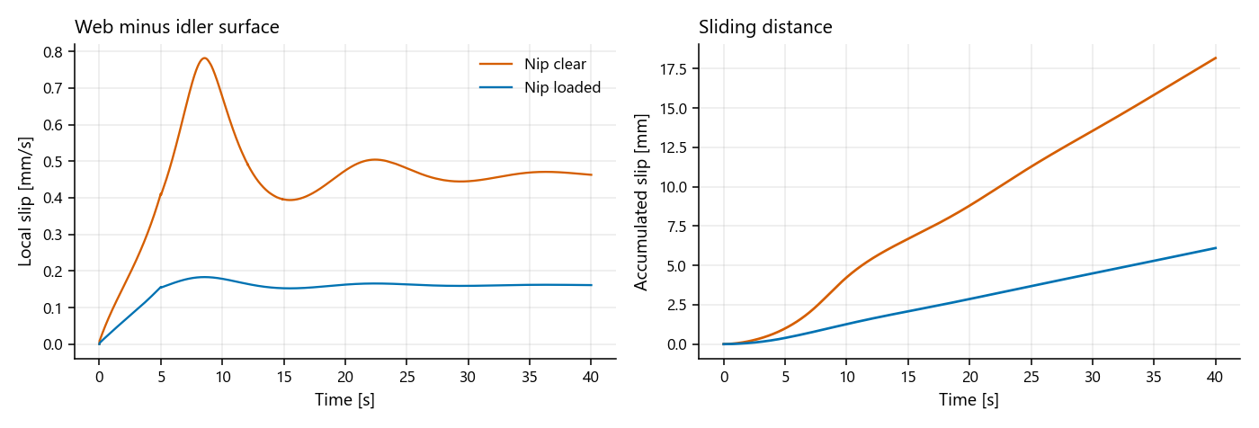
Figure 4. Startup with the nip clear versus loaded: incoming tension dips to 255 N and peak local slip falls from 0.78 to 0.183 mm/s.
Why does slip never reach zero, even with the nip loaded? The friction law. Classical Stribeck behaviour, reviewed by Olsson and colleagues, falls from higher low-speed friction to a lower sliding value, with a signed curve discontinuous at zero velocity. That discontinuity forces stick/slip switching on the solver. Our Triple S regularization replaces it with smooth transitions, continuous in force and slope at zero slip.
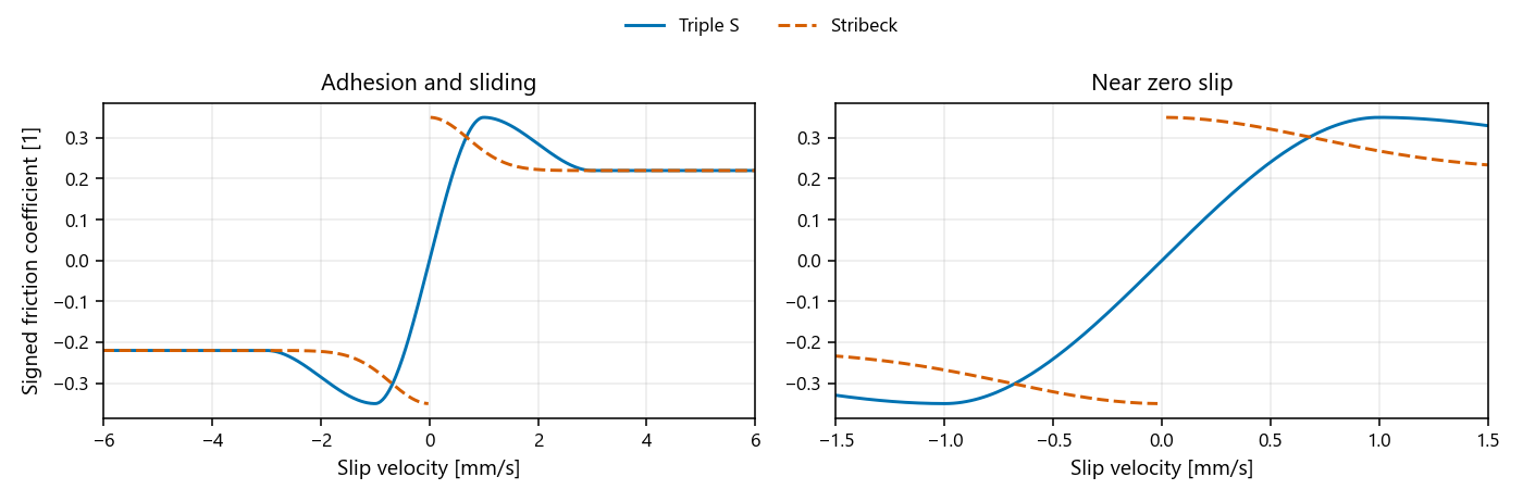
Figure 5. Triple S replaces the zero-speed discontinuity with an adhesion-slip region requiring finite slip for traction.
Baseline adhesion peaks at 0.35 at 1 mm/s; sliding reaches 0.22 at 3 mm/s. The price of smoothness is that traction needs finite slip, so a residual creep exists by construction and its absolute value depends on the assumed curve parameters. Independent compression springs along the nip face approximate the contact footprint, integrated force and load-resultant position. They do not resolve an elliptical patch, cross-face shear or a contact-stress field, and omit finite-face overlap and wrapped-arc checks.
The following alignment and friction comparisons fix centre compression at 1 mm. Yaw turns the idler about the vertical, keeping its ends level. Tram tilts it about the machine direction, lifting one end. Alignment angles of 1.15, 2 and 3 degrees are deliberate stress cases, not tolerances.
Crossing the Axes: Yaw
Why does load fall at an unchanged housing setting? Crossing the idler and nip axes opens a parabolic gap toward both face edges, reducing compression. Ideal concentric cylinders retain this geometry as they rotate, so crossing alone produces no once-per-revolution load ripple.
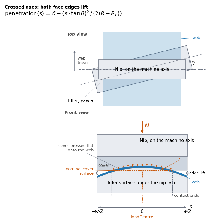
Figure 6. Yaw lifts both face edges; the approximate footprint stays centred.
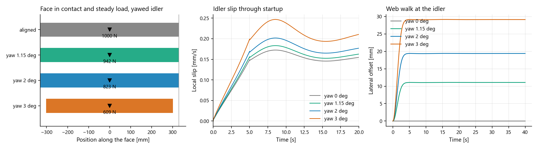
Figure 7. At fixed centre compression, yaw lowers load and shifts the web's steady position.
At 3 degrees, 1.20 mm edge lift exceeds the 1 mm compression. The outer 28 mm of each nip face edge loses contact. Load falls from 1000 N aligned to 609 N: a gauge reads 39% less force despite the unchanged housing setting. The nip still adds about 213 N of adhesion capacity to the wrap's traction. Accumulated slip rises from 5.80 to 7.90 mm, while lateral displacement grows much more visibly.
An entering web tends toward perpendicularity with the receiving roller, the normal-entry principle described in Shelton's Lateral Dynamics of a Moving Web. Offset settles near 11.1 mm at 1.15 degrees and 29.1 mm at 3 degrees. The latter reaches a minimum nominal edge margin of -1.3 mm, indicating overhang whose loss of support the lateral model does not resolve.
The crossed nip applies opposing lateral friction. Each contact shares its friction capacity between longitudinal and cross-machine motion. At the original settings, nip action reduces offset by less than 0.1 mm: sufficient traction still coexists with substantial tracking error.
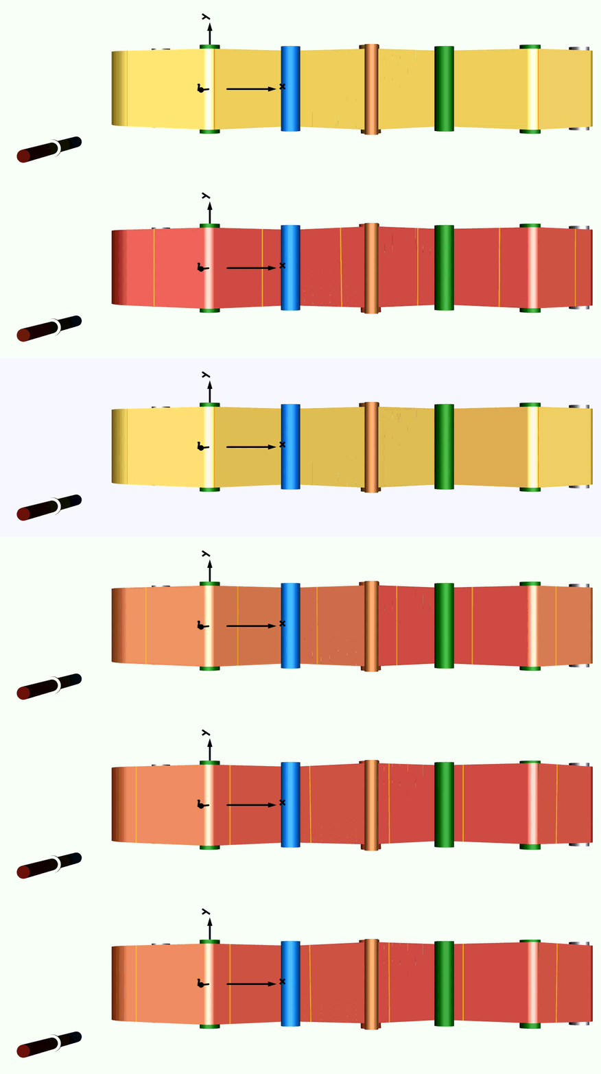
Figure 8. Yawed startup toward a displaced steady position.
Increasing Nip Friction
Can stronger friction change that balance? At 20 mrad yaw, we scale only nip adhesion and sliding coefficients by 1, 2 and 3: pairs of 0.35/0.22, 0.70/0.44 and 1.05/0.66. Other roller friction and slip-velocity thresholds stay fixed. These assumed sensitivity settings represent no particular cover material. Contact load remains about 942 N.
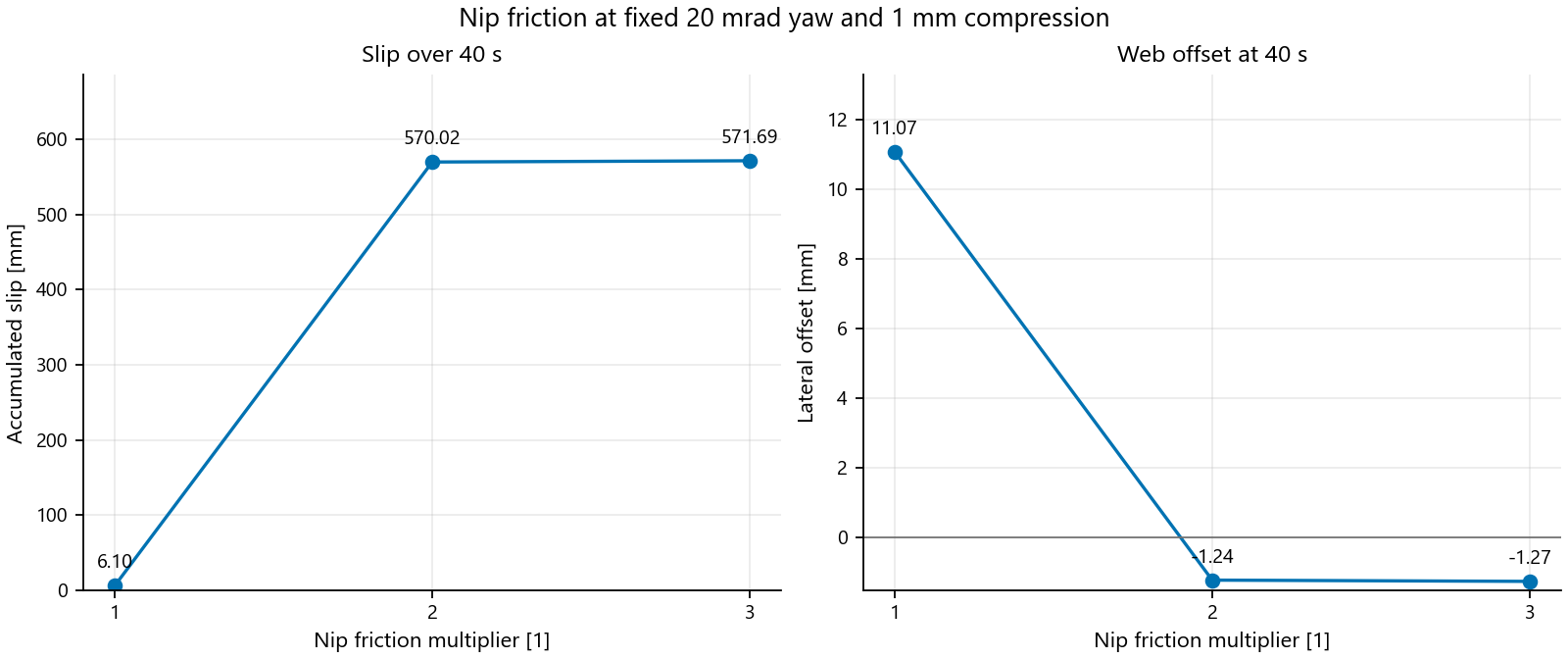
Figure 9. Stronger passive steering accompanies sharply increased idler slip. Negative offset is opposite the baseline side of centre. Markers show three simulated settings.
Doubling friction moves final offset from +11.07 to -1.24 mm; tripling leaves it near -1.27 mm. Accumulated idler slip over 40 s rises from 6.10 to about 570–572 mm, roughly 94 times the baseline. The web ends closer to centre, on the opposite side, with much greater longitudinal slip.
Nip orientation stays fixed, without lateral-position feedback. Both contacts divide friction capacity between longitudinal and lateral motion, coupling steering to slip. These settings demonstrate a tradeoff, without establishing an optimum coefficient or locating the response transition.
Tilting the Axis: Tram
Could high, steady load hide misalignment? Tram opens a wedge: one idler end rises into the nip cover while the other falls away. Contact and its load resultant shift toward the raised end.
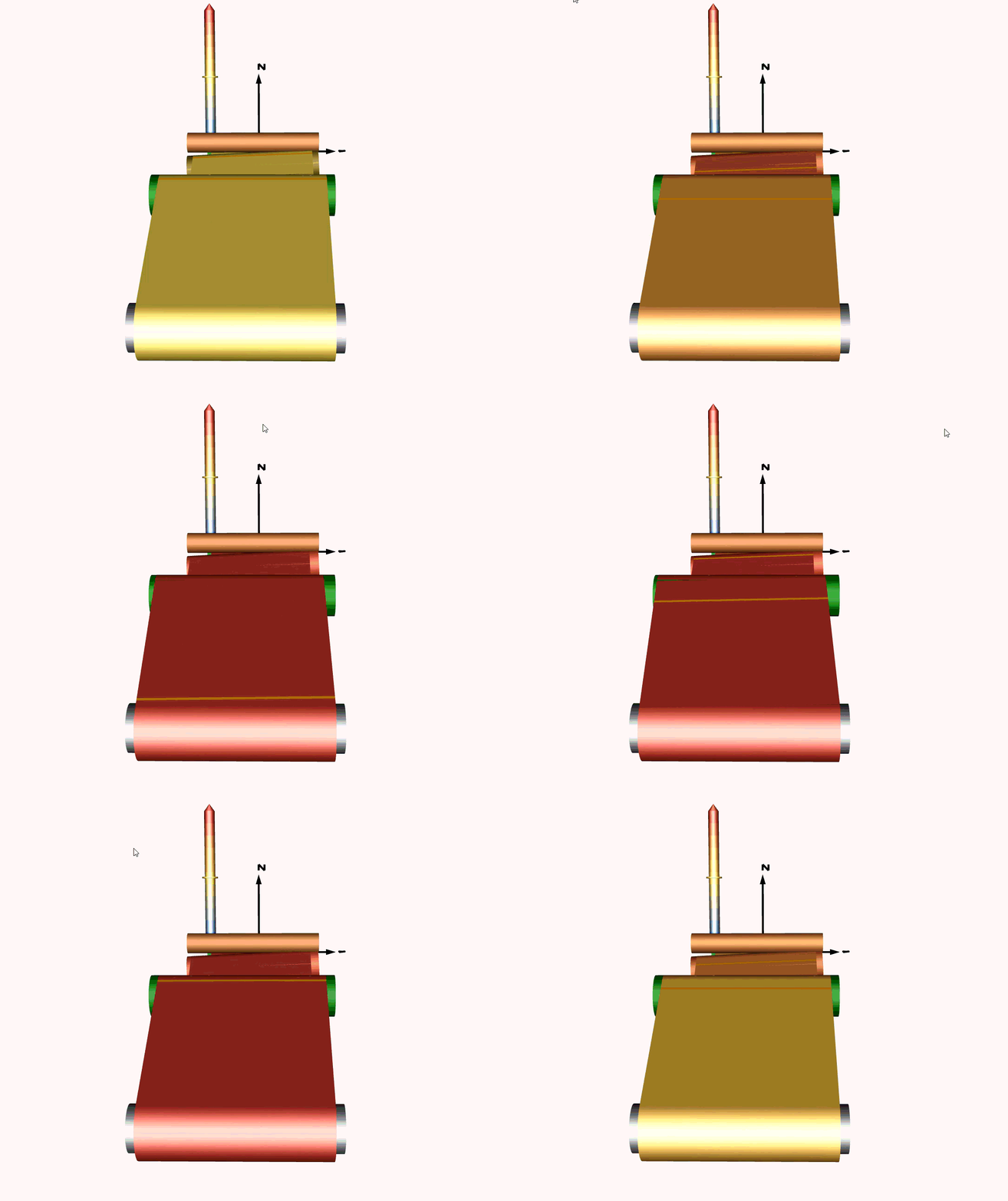
Figure 10. One nip face end lifts clear while the raised end compresses the cover.
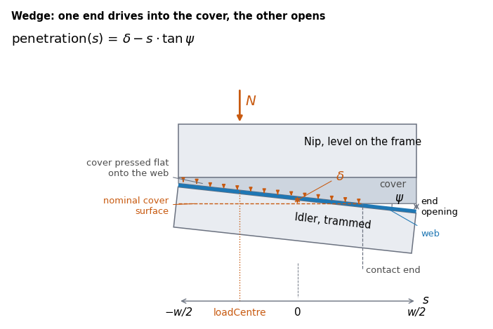
Figure 11. Asymmetric contact under a rigid, level housing.
At the rigid housing's fixed centre-line distance, tram redistributes compression rather than relieving it: the raised end digs deeper into the cover while the lowered end lifts clear. Below about 0.17 degrees the face stays fully in contact and total load holds at the aligned 1000 N; past that, the shrinking footprint carries the same centre-line penetration over less width, and load climbs.
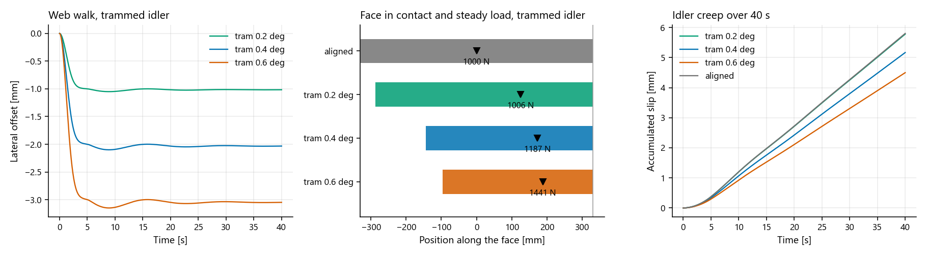
Figure 12. Tram shifts contact toward one end while reducing simulated creep. Load rises as the footprint narrows, on a rigid, imposed-compression housing.
At 0.2, 0.4 and 0.6 degrees, the footprint narrows from 660 mm aligned to 617, 474 and 426 mm; the load resultant moves 124, 172 and 188 mm off centre. Nip load climbs from 1000 N aligned to 1006, 1187 and 1441 N: a rigid housing turns a fraction of a degree of tram into load 44% above the 1000 N actuator-force cap, without any change at the compression gauge. A compliant or self-aligning housing would cap this instead of letting it climb; this model has neither.
Through the entering span, descending from the dancer at 34 degrees, tram steers toward the low end. Offsets settle between -1.0 and -3.1 mm, opposite in sign and much smaller than the yaw cases. Lower creep and higher total nip force therefore coexist with asymmetric contact and displacement in this idealized model. Neither reading establishes correct alignment.
Finding a Local Tension Disturbance
Does low accumulated slip mean steady loading? We align the idler and drive the nip drum with a 0.3 mm eccentricity: its centre orbits the bearing axis once per revolution, 0.6 mm peak-to-peak on this ideal circular drum.
Slip barely changes: 5.92 mm over 40 s versus 5.80 mm aligned and concentric. Yet nip load cycles between about 700 and 1300 N.
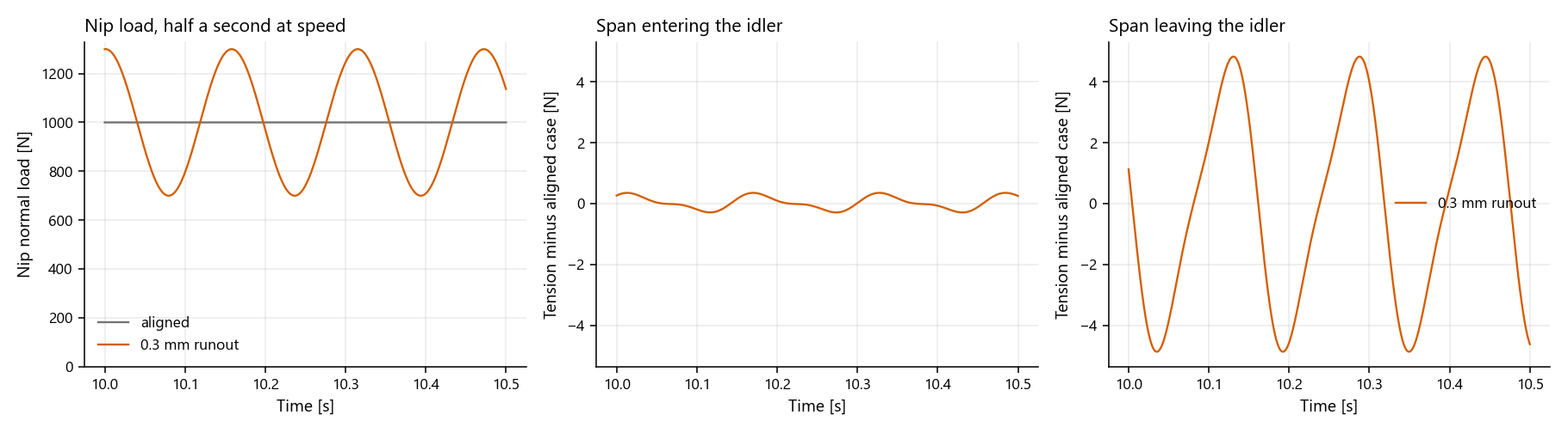
Figure 13. Nip load at the 0.3 mm eccentricity amplitude. Tension ripple is 9.7 N peak-to-peak downstream versus 0.69 N entering the idler. Tension panels show differences from the aligned, concentric case on matching vertical scales.
Compression gains and loses 0.3 mm per revolution. At speed v = 2 m/s and
nip radius R = 0.05 m, the disturbance frequency is f = v/(2πR) = 6.37 Hz.
Ripple at the controlled span farther upstream is only 0.73 N peak-to-peak,
understating the local response.
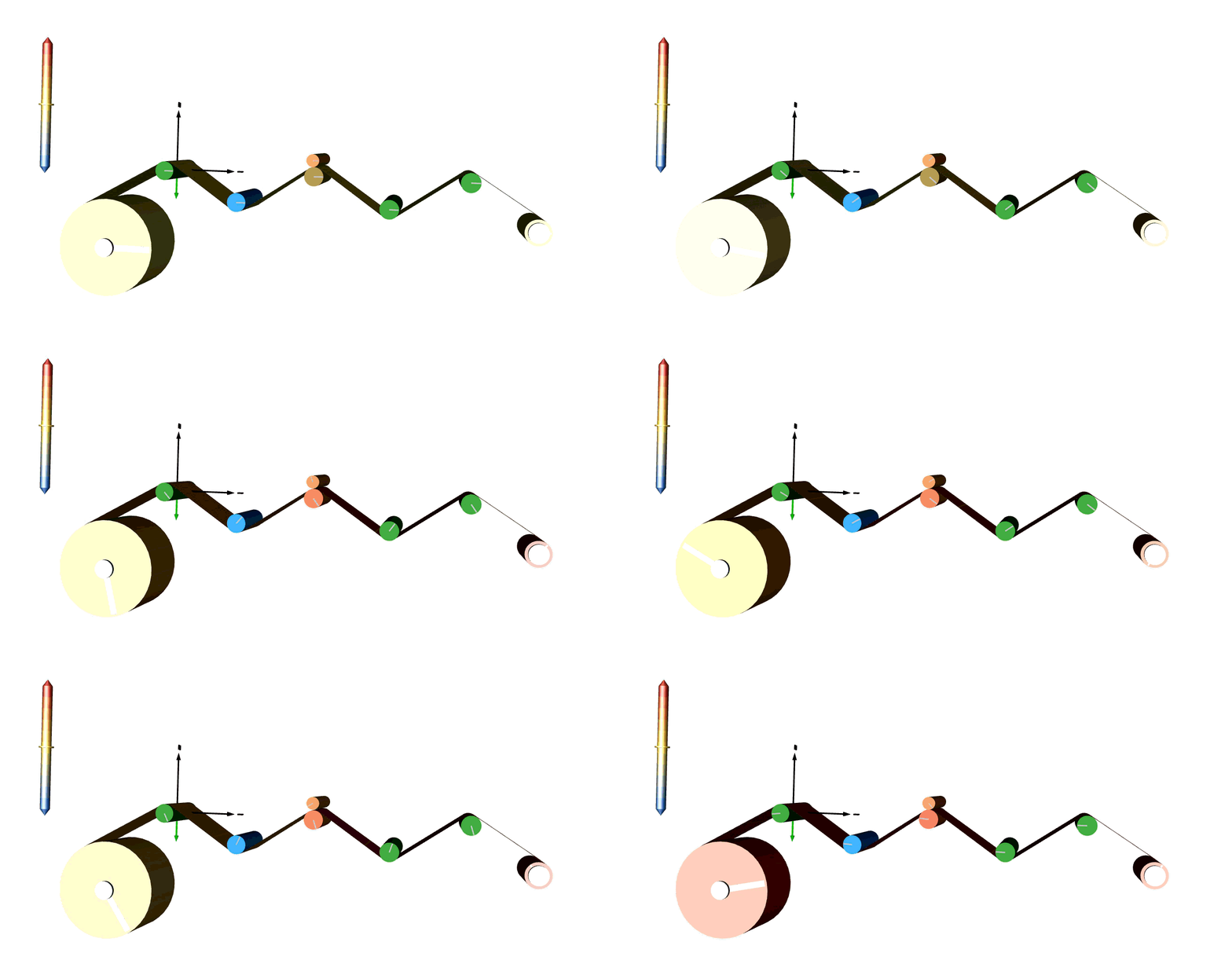
Figure 14. Nip eccentricity adds a cyclic disturbance; web colour shows tension.
This gives an engineer reason to inspect local tension alongside the controlled upstream signal. A disturbance at nip turning frequency makes runout a candidate, but does not uniquely identify it. Load range here follows the assumed cover law; tension amplitudes lack machine calibration. Angular runout is excluded.
Using the Results
So, has more nip force solved the problem? It has fixed the slip reading. Accumulated slip fell 66% and the web stayed 11 mm off centre. Lateral steering comes from idler geometry, and nip load leaves that geometry alone. The slip gauge improved because traction improved, which says nothing about where the web runs.
Each experiment separates a variable that a single reading conflates:
- Nip load buys traction. Slip down 66%, offset down 0.7%.
- Nip friction buys steering, paid in slip. Doubling the coefficient moves the web from +11.07 mm to -1.24 mm, while idler slip rises 94×.
- Yaw at 3 degrees lifts both face edges and drops measured load 39% with the housing setting unchanged. The gauge reads the geometry, not the actuator.
- Tram shifts the footprint to one end, moves the load resultant up to 188 mm off centre, and raises load 44% above the 1000 N aligned reading at the same housing setting.
- Runout leaves accumulated slip almost unchanged (5.92 versus 5.80 mm) while nip load swings between 700 and 1300 N. The controlled upstream span sees 0.73 N of ripple against 9.7 N downstream.
The pattern is the same each time. One measurement improves, or holds steady, while a coupled quantity moves. A coupled model with controls active exposes that second quantity before anyone treats the first as a resolution. Fix the alignment first. Then spend nip force on traction, and measure both.
The study establishes neither safe operating limits nor wrinkle onset. Wrinkle prediction needs cross-width stress and structural analysis beyond this lumped model. Machine-specific results also need representative friction and contact properties.
References
- J. J. Shelton, Lateral Dynamics of a Moving Web, PhD dissertation, Oklahoma State University, 1968. OSU repository.
- Yun, Lee, Jang, Kim, Kim and Lee, "Sensor-Efficient Estimation of Lateral Web Position in Roll-to-Roll Film Processing," Polymers 17(21):2907, 2025. doi:10.3390/polym17212907.
- J. Kim, K. Kim, H. Kim, P. Park, S. Lee, T. Lee and D. Kang, "Experimental Validation of High Precision Web Handling for a Two-Actuator-Based Roll-to-Roll System," Sensors 22(8):2917, 2022. doi:10.3390/s22082917.